


Search and Sample Return Project
The goal of this project were to use perception and decision steps to control a rover in a simulator. Perception occurs via using computer vision techniques to determine navigable terrain and then make decisions to take Action on the rover.
Its the first project of the Robotics Nano Degree program. I ran my simulator in 1600x1200 resolution. Different resolution may impact on the performance of the model in this project.
Notebook Analysis
The first step was to perform some analysis in a jupyter notebook on sample/calibration data.
Run the functions provided in the notebook on test images (first with the test data provided, next on data you have recorded). Add/modify functions to allow for color selection of obstacles and rock samples.
This step involved loading the data

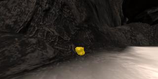
and then doing a perspective transform to get a birds eye view.


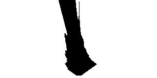
A function color_thresh was provided to do color thresholding (defaulted to RGB channels > 160). It was used as the basis to create an obstacle_thresh method (which selected the inverse ie RGB color channels <= 160). A rock_thresh method was created that selected between min and max color channels. The image color channels are converted from RGB to YUV before being used via warped_rock_yuv=cv2.cvtColor(warped_rock, cv2.COLOR_RGB2YUV).


Populate the process_image() function with the appropriate analysis steps to map pixels identifying navigable terrain, obstacles and rock samples into a worldmap. Run process_image() on your test data using the moviepy functions provided to create video output of your result.
1) Define source and destination points for perspective transform
dst_size = 5
bottom_offset = 6
source = np.float32([[14, 140], [301 ,140],[200, 96], [118, 96]])
destination = np.float32([[img.shape[1]/2 - dst_size, img.shape[0] - bottom_offset],
              [img.shape[1]/2 + dst_size, img.shape[0] - bottom_offset],
              [img.shape[1]/2 + dst_size, img.shape[0] - 2*dst_size - bottom_offset],
              [img.shape[1]/2 - dst_size, img.shape[0] - 2*dst_size - bottom_offset],
              ])
2) Apply perspective transform
a warped image is created using the source and destination points from above warped = perspect_transform(img, source, destination)
3) Apply color threshold to identify navigable terrain/obstacles/rock samples
The thresh_min and thresh_max values were determined via an interactive cell in the notebook.
threshed = color_thresh(warped)
obstacle_threshed = obstacle_thresh(warped)
warped_yuv=cv2.cvtColor(warped, cv2.COLOR_RGB2YUV)
thresh_min=(0, 38, 153)
thresh_max=(145, 148, 170)
rock_threshed = rock_thresh(warped_yuv, thresh_min, thresh_max)
4) Convert thresholded image pixel values to rover-centric coords
xpix, ypix = rover_coords(threshed)
xpix_obst, ypix_obst = rover_coords(obstacle_threshed)
xpix_rock, ypix_rock = rover_coords(rock_threshed)
5) Convert rover-centric pixel values to world coords
world_size = data.worldmap.shape[0]
scale = 12
xpos = data.xpos[data.count]
ypos = data.ypos[data.count]
yaw = data.yaw[data.count]

xpix_world, ypix_world = pix_to_world(xpix, ypix, xpos, ypos, yaw, world_size, scale)
xpix_world_obst, ypix_world_obst = pix_to_world(xpix_obst, ypix_obst, xpos, ypos, yaw, world_size, scale)
xpix_world_rock, ypix_world_rock = pix_to_world(xpix_rock, ypix_rock, xpos, ypos, yaw, world_size, scale)
note: data.count contains the current position in index for the video stream.
6) Update worldmap (to be displayed on right side of screen)
for obstacle_x_world, obstacle_y_world in zip (xpix_world_obst, ypix_world_obst):
    data.worldmap[obstacle_y_world, obstacle_x_world, 0] += 1
for rock_x_world, rock_y_world in zip (xpix_world_rock, ypix_world_rock):
    data.worldmap[rock_y_world, rock_x_world, 1] += 1
for navigable_x_world, navigable_y_world, in zip(xpix_world, ypix_world):
    data.worldmap[navigable_y_world, navigable_x_world, 2] += 1
7) Make a mosaic image
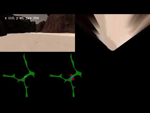
A mosaic image was created showing the rover camera image, warped image, ground truth (with rover location and direction arrow) and another ground truth (showing the current obstacle and navigable mapping)
Test video follows
Autonomous Navigation and Mapping
Fill in the perception_step() (at the bottom of the perception.py script) and decision_step() (in decision.py) functions in the autonomous mapping scripts and an explanation is provided in the writeup of how and why these functions were modified as they were.
perception_step()
This step utilised the efforts from the notebook analysis, described above. The Rover Worldmap was not updated if there was observable pitch or roll (eg > + or - 1 degree).
In addition rover polar coordinates were derived and saved against the passed Rover object for both navigable areas and observed rocks (if no rocks observed set to None).
decision_step()
This is the challenging part of the project.
stop and forward were the two default rover modes supplied. For this project stuck, rock and reverse were added.
forward was modified to have a left hugging biases by adding 65% of the standard deviation of the navigable angles, as long as there had been some travel time either initially or after being stuck.
The rover enters stuck mode if the rover stays in the same position, whilst not picking up a rock, for 5 seconds. If still stuck after 10 seconds, then reverse mode is tried. After 15 seconds, stuck and reverse are reset before trying stop mode.
stuck mode tries rotating if there is an obstruction in front, moving forward if steering not locked full left or right whilst going slow, and breaking if steering is locked full left or right. It will reset to forward if movement is restored.
reverse mode rotates randomly between 30 and 180 degrees after setting the brakes and reducing velocity to zero. Once its within + or - 15 degrees it sets mode to forward. If reverse mode is in-affective to sets it to stop mode.
If a rock is observed, some false positives are ignored, as well as distant rocks before being placed into rock mode. Whilst the rock is not close, it tries to navigate closer towards it before breaking or coasting closer. The algorithm still requires more refinement.
Note: All my testing and running in Autonomous mode was done at 1600x1200 resolution.

Search and Sample Return Project

This project is modeled after the NASA sample return challenge and it will give you first hand experience with the three essential elements of robotics, which are perception, decision making and actuation. You will carry out this project in a simulator environment built with the Unity game engine.
The Simulator
The first step is to download the simulator build that's appropriate for your operating system. Here are the links for Linux, Mac, or Windows.
You can test out the simulator by opening it up and choosing "Training Mode". Use the mouse or keyboard to navigate around the environment and see how it looks.
Dependencies
You'll need Python 3 and Jupyter Notebooks installed to do this project. The best way to get setup with these if you are not already is to use Anaconda following along with the RoboND-Python-Starterkit.
Here is a great link for learning more about Anaconda and Jupyter Notebooks
Recording Data
I've saved some test data for you in the folder called test_dataset. In that folder you'll find a csv file with the output data for steering, throttle position etc. and the pathnames to the images recorded in each run. I've also saved a few images in the folder called calibration_images to do some of the initial calibration steps with.
The first step of this project is to record data on your own. To do this, you should first create a new folder to store the image data in. Then launch the simulator and choose "Training Mode" then hit "r". Navigate to the directory you want to store data in, select it, and then drive around collecting data. Hit "r" again to stop data collection.
Data Analysis
Included in the IPython notebook called Rover_Project_Test_Notebook.ipynb are the functions from the lesson for performing the various steps of this project. The notebook should function as is without need for modification at this point. To see what's in the notebook and execute the code there, start the jupyter notebook server at the command line like this:
jupyter notebookThis command will bring up a browser window in the current directory where you can navigate to wherever Rover_Project_Test_Notebook.ipynb is and select it. Run the cells in the notebook from top to bottom to see the various data analysis steps.
The last two cells in the notebook are for running the analysis on a folder of test images to create a map of the simulator environment and write the output to a video. These cells should run as-is and save a video called test_mapping.mp4 to the output folder. This should give you an idea of how to go about modifying the process_image() function to perform mapping on your data.
Navigating Autonomously
The file called drive_rover.py is what you will use to navigate the environment in autonomous mode. This script calls functions from within perception.py and decision.py. The functions defined in the IPython notebook are all included inperception.py and it's your job to fill in the function called perception_step() with the appropriate processing steps and update the rover map. decision.py includes another function called decision_step(), which includes an example of a conditional statement you could use to navigate autonomously. Here you should implement other conditionals to make driving decisions based on the rover's state and the results of the perception_step() analysis.
drive_rover.py should work as is if you have all the required Python packages installed. Call it at the command line like this:
python drive_rover.pyThen launch the simulator and choose "Autonomous Mode". The rover should drive itself now! It doesn't drive that well yet, but it's your job to make it better!
Note: running the simulator with different choices of resolution and graphics quality may produce different results! Make a note of your simulator settings in your writeup when you submit the project.
Project Walkthrough
If you're struggling to get started on this project, or just want some help getting your code up to the minimum standards for a passing submission, we've recorded a walkthrough of the basic implementation for you but spoiler alert: this Project Walkthrough Video contains a basic solution to the project!.


